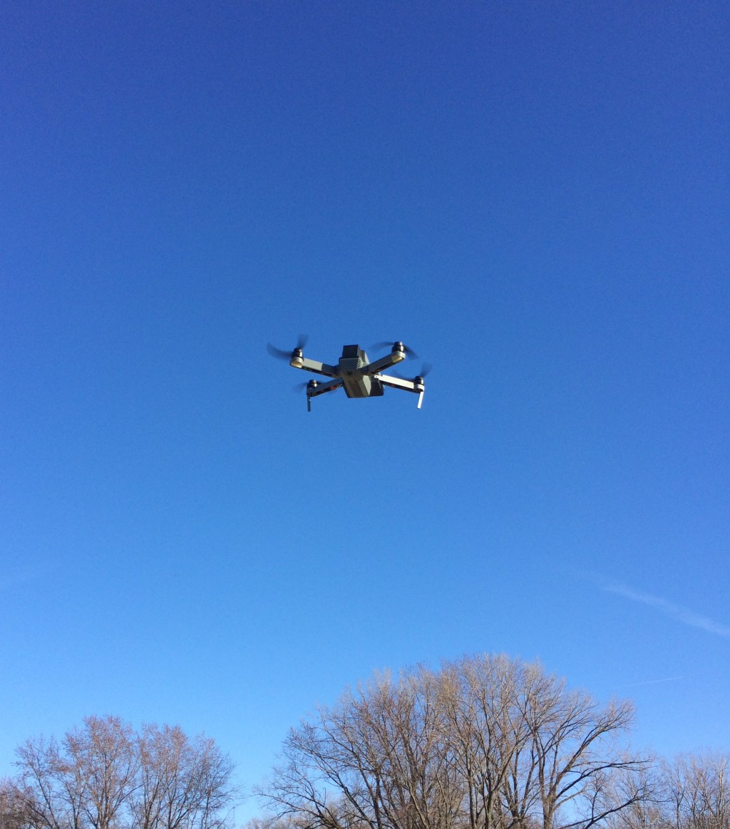
After extensive design consideration and 3D printing, it was time for the models first flight! Above is a picture of it hovering while I struggled to take a one handed picture from my cellphone.
To allow for such a stable flight, inside the quad copter is a flight controller made by dji. To allow for the stable flight characteristics, the flight controller I used contains inner dampening, 3-axis gyroscope, 3-axis accelerometer, and a barometer. These components alone are not enough to stabilize the quad copter. The flight controller also contains a control system to effectively smooth out the flight. To smooth out the flight, error between user input and output to the motors is minimized with PID controllers. This error is calculated by taking the difference between user input and output to the motors.
With winds at 10-15 mph, flight time was 7 minutes. This duration could simply increased by increasing the amp hour rating on the battery, however, the size of the quad copter limits the battery size to 1300mah.
Design changes
The quad copter flew great, however, the electronics had no place to mount to. I solved this problem by designing built in mounting tabs where the power distribution board and flight controller could rest.

The receiver also needed a mounting location. Since this is a sensitive component, I designed a small enclosure where the receiver could sit to prevent contact between it and any loose wiring. Antenna exit cutouts were also considered to divert them away from all electronics.

The antenna routing from the cutouts can be seen below. Placing the antenna around the exterior of the model would ensure that they were out of the way and protected.

When flying the model, key information such as battery status was crucial to safely landing when the battery discharged to low. The flight controller included a data output/ LED indicator which could be mounted to the exterior of the model. I designed a cutout at the bottom of the model which would both protect and house this LED. The LED also had a built in micro USB in its circuitry, so I also designed a cutout to easily access it for quick model programming.

Below is the enclosure I came up with to house the LED/ data output circuit. I essentially re-cased the LED indicator to fit inside the base plate of the model.


Leave a comment