3D printing Process
Below is a picture of the squeeze wrench getting printed. This print was done at 100% scale, 50% infill, and 2 mm wall thickness.


Problems With Overhang on the Flexible Portion

Gear Mechanism

Design Changes
Design changes were made based off of what I learned from the first print. Changes to the socket gear mechanism, and the housing were made. Material was also taken out of the handle to speed up print time for printing with 100% infill.

After printing, I noticed that the flat cap portion of the wrench was causing issues with overhang of the material. Overhang occurs when the plastic tries to bridge a gap that is too large, and does not cool fast enough to effectively bridge it. The cap was partially fusing itself to the gear mechanism. To solve this problem, I created a large chamfer at the top portion of the gear so that the plastic would only have to overhang incrementally. The chamfer also got rid of the large stress concentration before the top socket.

The squeeze mechanism did work, however, as expected it skipped under any practical application of force. I increased the amount of teeth on the flexible portion to 4, and made them more pronounced.

Overhang was also an issue on the flexible portion of the wrench housing. With the original design, the support material was not sticking properly to the wrench when 3D printed. I decided to remove the bottom segment to force the printer to print directly on the build platform.
Flexible Portion Re-Design

Testing
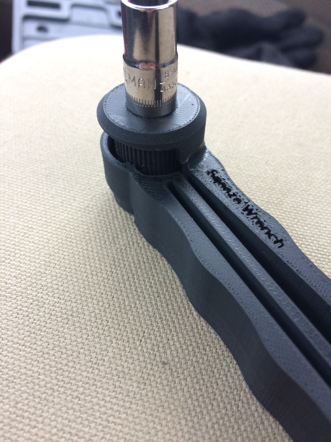
The wrench was designed to accept a standard 3/8″ socket. I decided to scale the wrench down 67% to accept a standard 1/4″ socket. Below is an image of the 1/4″ wrench with all the design changes. Note that the teeth have not been re-designed in this image.


