What is 3D printing?
More specifically, what does a 3d printer look like in a home setting? Well… think of a very sophisticated hot glue gun; a glue gun controlled by CNC (computer numerical control). Yes, the same CNC that you see in machine shops. In the case of a a CNC router, we are removing material from what is called a stock piece of material. This stock is generally just a block of metal, or even a block/ sheet of plastic. This process is subtractive. In the case of 3D printing, we are adding material, building layer by layer of plastic. So CNC routing is a subtractive manufacturing process, while 3D printing is additive. Thinking back to the hot glue gun analogy above, my 3D printer is formally considered an FDM 3D printer (fused deposition modeling). We are using a nozzle to change the state of a plastic, much like what you see on a hot glue gun.
How can I improve this piece of technology?
Before sharing my thesis for improvement, I must say that the original design is actually amazing in terms of its simplicity and low cost. Though, I am not really concerned about these two things since I am not the one mass producing this 3D printer.
In the 3D printing world, you will hear companies advertising hot end products by using lingo such as “all metal”. This means that it is all metal (as it was before), but the teflon piece is further away from any heating action to prevent damage to it. When material is extruded through the nozzle of my 3d printer, the temperature gradient is to narrow for sufficient unrestricted flow. The plastic material going into the nozzle was melting before hitting the nozzle, thus creeping up the nozzle tube. In addition, it is known that teflon starts breaking down at temperatures >= 230 degrees C. The teflon piece was being consumed by the hot plastic that would creep up the nozzle tube. Teflon is crucial in this tool head design and many other manufacturers designs because it is very slippery, and it allows the plastic filament to slide past with ease. When it breaks down, the friction increases, and the teflon piece must be replaced. To solve this problem, a cooling fin was designed to reduce the temperature before the teflon component.
What did I do to solve this problem?
Designed a heat sink to keep things cool where needed.
Desired design attributes
- Compact
- does not collide with printer frame
- retrofit to current nozzle components
- Light weight
- to allow for quick prints
- Efficient
- high fin efficiency/ fin temperature distribution
- Household materials
- circuit board heat sinks
- Manufacturable
- available tools
Design Process
To my luck, an old flat screen TV circuit board was laying around. The circuit board had multiple aluminum rectangular fin heat sinks to choose from (6 fins per heat sink). Each heat sink was being used to remove power from a number of voltage regulators. However, plucking a heat sink from this circuit board constrained me with my design. The length and width of the heat sink needed to be altered to fit my design requirement, which was to remove 40 watts of heat from the nozzle. 40 Watts was determined with a kil-o-watt wall plug power meter.

Throwing necessary engineering equations into a spreadsheet, my design resulted in 30mm wide, by 8mm long cooling fins, with an existing fin thickness of 1.25mm. These fins had a resulting effectiveness of 4.32, and an efficiency of 99%, and are capable of removing the required 40 watts of heat. To maintain a compact foot print, a cooling fan was needed to increase the average convection coefficient to 44 W*m^-2*K^-1. A fan with a CFM (cubic feet per minute) rating of 4.9 was sized according to a few design constraints:
- Had to fit around the heat sink, which had a rectangular cross section of 32mm x 15mm.
- Achieve the necessary convection coefficient
- Compact
- 3D printable
Behold! the “Super Duct I 40W” ! Its compact, only 25mm long x 34mm wide x 30mm tall! Achieves the necessary coefficient, is 3D printable, and fits around the heat sink! But what about testing it?

Fin Fabrication


Testing
In the case of this design, 40 watts of power is removed. This amount of power was decided by how much power (worse case) would be input into the nozzle at its max temperature of 260 °C. I wanted to test my design, so I placed a fan to test and gauge how a convective source would affect the heat up process. To my surprise, when I set the nozzle temperature to 260 °C, the printer could not reach it. I was afraid that this would happen since the heat sink is parasitic to the nozzle function.
Solution:
insulate the nozzle with fiberglass insolation.


The fiberglass insulation allowed the nozzle to reach its maximum temperature of 260 °C while the fan was running.
The fan arrived and duct was printed. I turned the printer nozzle to 260 °C and the nozzle was able to reach the temperature with the 3D printed fan duct. I then fed filament through the nozzle to test. My hope was that there would be no jams and that the plastic would flow out with little resistance. However, this was not the case. The cooling fin had cooled off the plastic, but cooled it to a rubbery consistency. I suspect that Ultimakers design works off the fact that the plastic is melted throughout to reduce the amount of friction. In my case, the plastic was still going beyond its glass transition temperature, but not far beyond.

Ultimaker Hot End
Stepping back a bit, if we take a look at the 3D printers original setup, we can see that at 260 °C temperature is maintained throughout the heat break. As the printer pushes hot plastic through, the plastic transitions inside the heat break taking advantage of its fluidity. This works, however over time the PTFE tube breaks down due to the filament creeping up and contacting it. When PTFE breaks down, it becomes less effective (coefficient of friction increases).
Over time I have also found that the plastic corrodes the heat break, especially when changing from PLA plastic to ABS. This leads to jams in the print head.

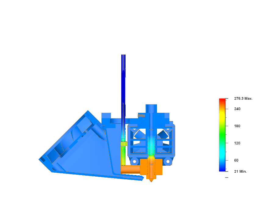
My Hot End Design
Below, you can see how my design responds to the applied 260 °C temperature. At the fin, temperatures are around 120 °C. At the heat break, temperatures are around 180 °C. At this temperature, ABS is in a glass transition state (about 97 °C and above) as mentioned above. At temperatures of 180 °C, the plastic is more fluid however it is still not fluid enough and thus the plastic adds too much resistance.

A Better Fin Design
My first fin design resulted in insufficient heat removal from the heat break. This resulted in jamming of the filament. To solve this problem, I decided to change the geometry by adding more fins. Of course when doing this, things such as the fan duct outlet area and overall packaging considerations change. All of this was accounted for in my Excel design spreadsheet.
New Fin Design Layout Considerations
Below is a thermal analysis of my first re-design. Already things look a lot better. I wanted to quickly see what an additional fin would do, so I used an additional 8mm fin set from the first test. This also forced me to design an aluminum coupler that would extend and give the fins something to pull heat from. This design was chosen mainly since I could easily fabricate the tube from an aluminum screw spacer.
Heat Break Material Change
One critical design change that I found very helpful was changing the heat break material. The original material was brass. By changing to stainless steel, heat flowed slower, and thus the temperature distribution improved (thermal conductivity of brass is greater than stainless steel).

Packaging Considerations
As I mentioned above, packaging was a concern for this project. The print head could not exceed a length of 50mm, or maximum allowable length for my printer. My first re-design was 56.1mm long, so I needed to consider a more compact solution. Also, I decided to use a new heater block made by E3D, so this altered the dimensions as well.
Fin Choices
From the circuit board, two types of fin lengths were available. One 12mm fin length, and one 17mm. I decided that I would run calculations for each when two fins were removed. I needed to remove two of the fins so it would keep the design compact.
Fin Design Trade Offs
I ended up going with the 12mm fin with two fins cut off. This would result in a print head length of 46.1mm. Heat transfer went down to 72.57 W (from 76.8 W), effectiveness rose to 5.69 (from 4.32) and efficiency fell slightly to 98.5% (from 99%).
Complete Package
Below is a rendering of my final design with a new filament cooling duct as well.

Thermal Analysis
Below is a cut away thermal analysis of the new design assembly.

Check out the design here!

Leave a comment