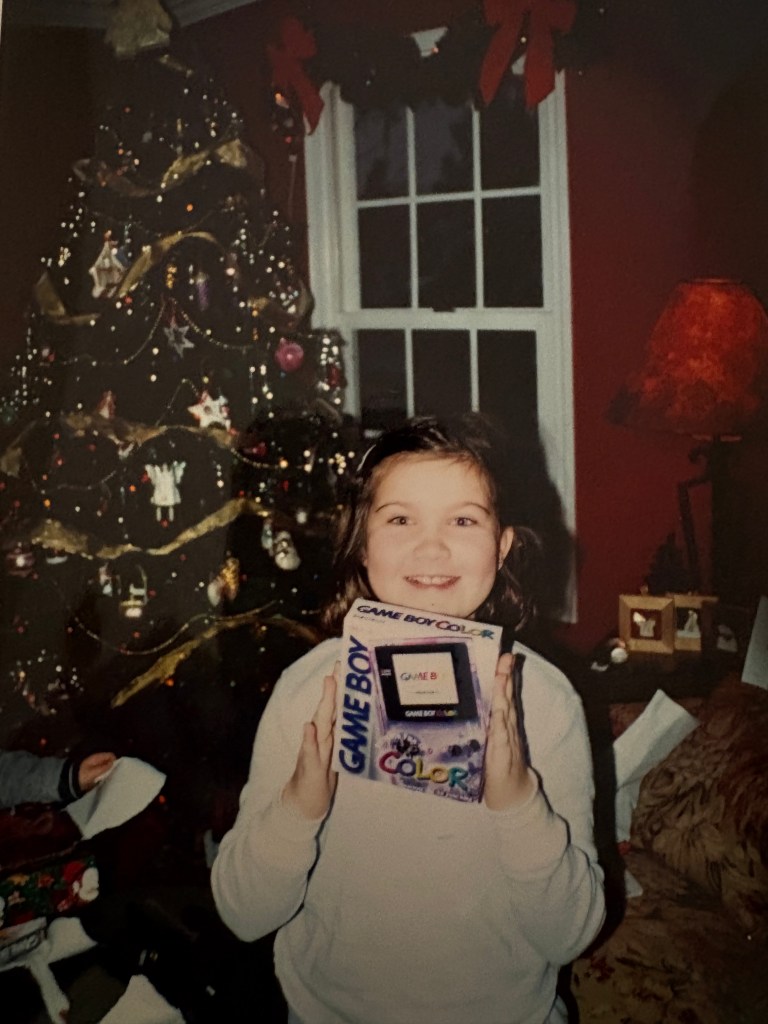
July 31st 1989 was the year the original Nintendo Gameboy was released. I was not around at that point in time but I do vividly recall the moment I first discovered portable handheld video game systems with the release of the Nintendo Gameboy Color back on October 21st 1998. Holiday season of 2001 my parents took my sister and I to Springhill mall to do some holiday shopping. I remember stumbling upon this strange looking kiosk in the middle of a clothing department store. It seemed out of place being located right alongside clothing and home goods. The kiosk had a bold out of place presence with a little colorful device like an appendage coming out it I had seen nothing like it before. The gameboy sat there with a small animated screen and I couldn’t comprehend how it worked. I grabbed hold of it and started playing and almost immediately knew that this was something big. I had no other intro to the device other then this moment.
October 1st 2025 Lego released set #72046 — a 1:1 replica of the original Nintendo Gameboy. I immediately knew that this Lego set would be something worth turning into the real thing. I have wanted to own an original Gameboy for some time but thought what a better way then to merge two things that brought me so much joy as a kid.
I first scoured the internet to see what others had done and came across Natalie’s post . She’s a very talented Melbourne based retro modder who I think created the very first Lego gameboy. What’s crazy is that this was just one small sliver of what she does. Definitely check out her other projects! For my project I drew inspiration from Natalie’s project and wanted to approach it in a similar way using the Gameboy Pocket motherboard. The Gameboy Pocket was basically an original DMG Gameboy brought to a smaller form factor. The main advantage is the packaging of the motherboard components. The MGB pocket has a CPU and combines the video ram into a single ram package IC. The original DMG has a CPU, video ram and separate ram package. This meant the MGB motherboard would be a great choice from a packaging standpoint since I was very space constrained in designing around the Lego set.
I really wanted to avoid adhesives and Ideally wanted everything to drop into place and give the same lego building experience but with a technical twist. I ran into my first challenge. This was with the fact that despite the Lego gameboy being a 1:1 model in theory, the models dimensions in reality were constrained by the Lego brick dimensions. I ordered a Gameboy game and tested the cartridge slot. Unfortunately I noticed bowing of the Lego set as I slid the game in. But honestly Lego really got close here and to be clear it was never their intent to actually slot in a real gameboy game. I decided that in order to slide a game in properly, I needed to design custom 3D printed lego pieces.
The buttons themselves had real clickyness and I felt like tactile membrane pads could be placed underneath. I knew that this was a very do-able project. I can’t say it enough but Lego really made an impressive set and took the time into adding so much great detail. For instance ports existed for the volume and contrast wheel. There was also a detailed spot for the power switch and EXT port. The one major limitation to this set however was the fact there was detail for some internals but that was all space that was taken up to add structure or maybe they were actually trying to virtually add some of the internal motherboard detail. Regardless I knew that further modification of the Lego model would be necessary, but I wanted to minimize this as much as possible to maintain a fun building experience.
I went heads down on a board design and began my journey into the retro modding world. Luckily the MGB has been thoroughly documented and there was already a project I was able to pull down from github. My strategy would be modifying a stock MGB schematic and of course starting from scratch on the PCB trace layout. There were a few things that would be new to this design. One would be the power source. I decided what better then to look at some existing Nintendo devices. I found that the Nintendo switch Joycon battery was actually a great candidate for this. It fit inside the dimensions of where the alkaline batteries would traditionally go. I decided that this would be charged via USBC. Even though I ensured charging via USBC, I also felt like it was important to have the ability to play without the need for a battery to allow for external power gameplay. The IC I chose had built in power path management so it could switch between charging the Joycon battery or if that wasn’t connected, it would switch to just providing USBC power directly to the system. The second major change was using a Gameboy Advance SP cartridge slot. This was much more compact and had the same number of pins as the original DMG slot. I also wanted to modernize the display and wanted to avoid having to mess around with screen contrast. the original DMG and MGB had a contrast wheel that despite boosting nostalgia points made for a sub par viewing experience. The selection for modern IPS screens was pretty good. I found a screen that would fit inside the Lego display and tested that out.
The circuit board was designed to fit the dimensions of the Lego display. My vision was for a drop in screen and motherboard module. Ideally this would drop in and then the externals such as the buttons, volume, power and speaker would get wired up and routed to their respective location.
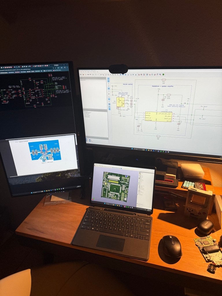
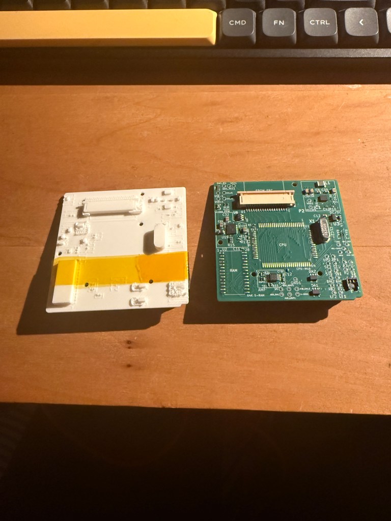
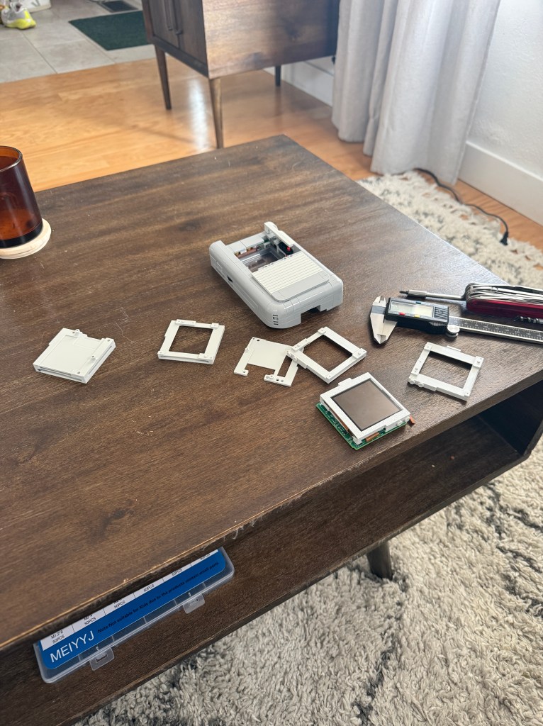
To validate the electronics packaging, I decided to 3D print the circuit board to ensure everything fit before committing to the long MFG lead times.
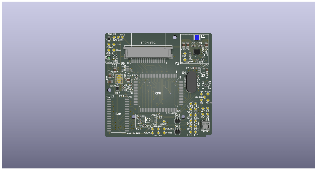
I actually must confess… Nimbus did most of the heavy lifting here. He called the shots on the CPU trace routings. Wasn’t me who generated this mess.
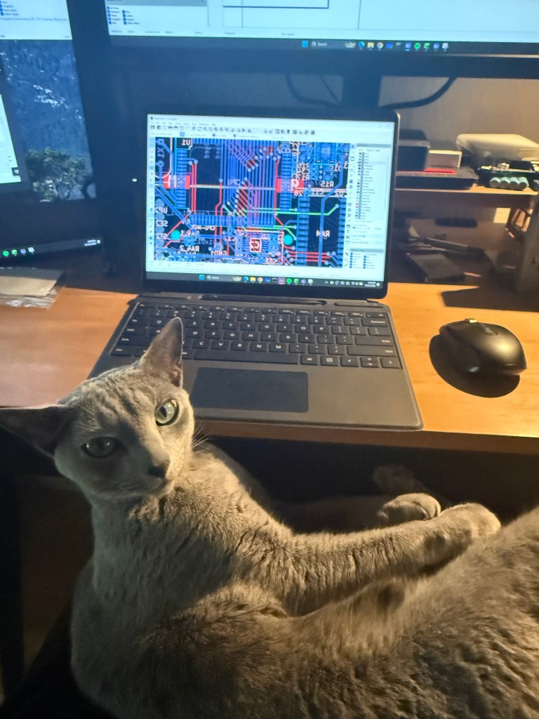
One of my favorite parts with PCB design is looking at the final 3D rendering. Being a Mechanical Engineer by trade, my mind lights up when I see anything emerging from the digital realm into physical reality. This was a huge challenge packaging and getting everything to route. Routing traces around the CPU and audio amplifier circuit was really pushing the limits of design possibility.
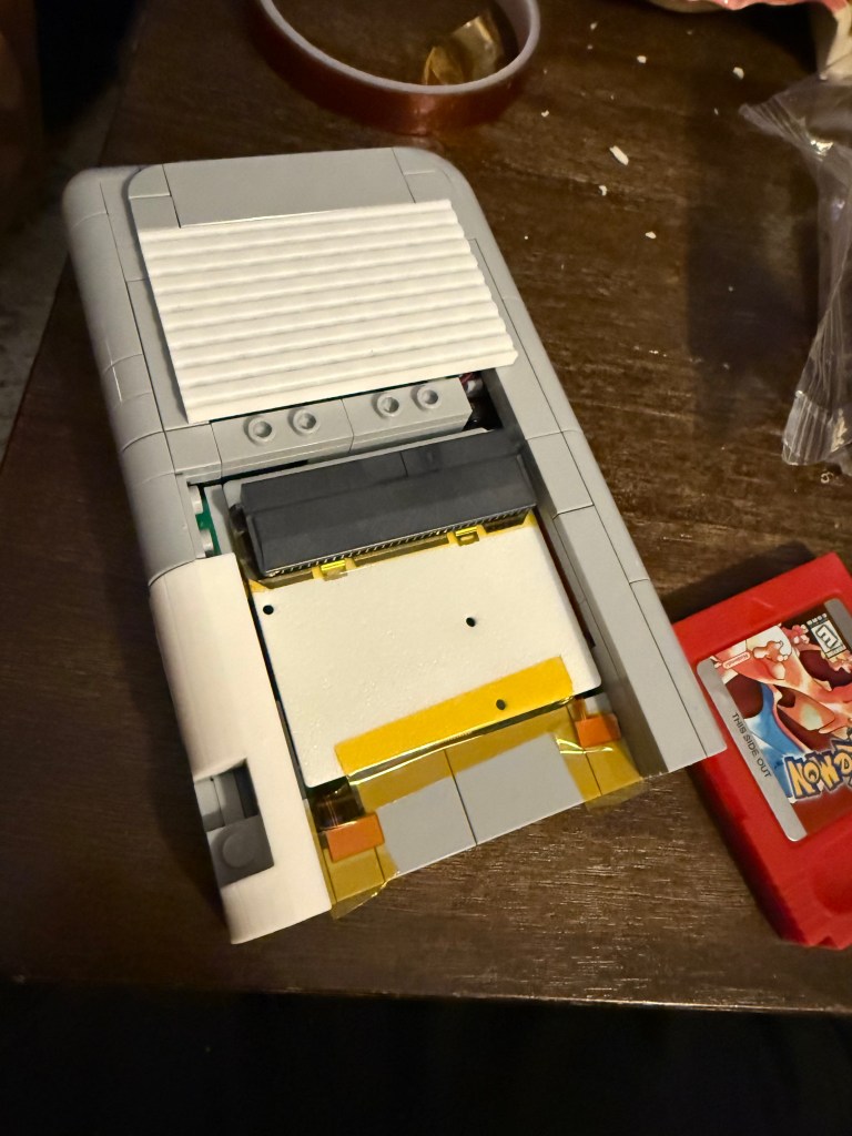
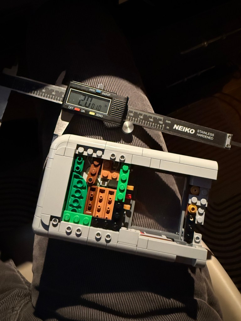
Now that I had the board designs off to the MFG, I had to focus more on the actual integration. This was actually a pretty fun process and was a lot of trial and error. A lot of the original Lego set had to be modified in order to get all the components packaged into it. I spent a lot of time removing and adding pieces but only wanted to add pieces in that came from the set.
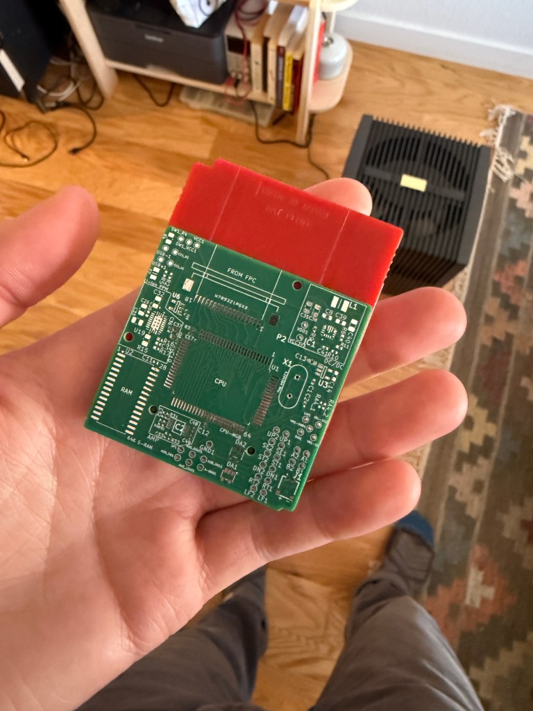
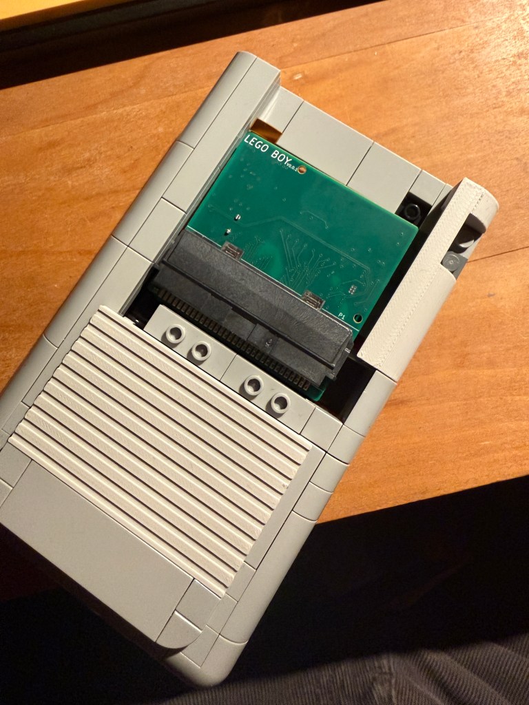
Now the really fun part. The board has arrived! It’s crazy going from 3D printed mockup to the real thing.
The board is slightly smaller then an actual gameboy game.
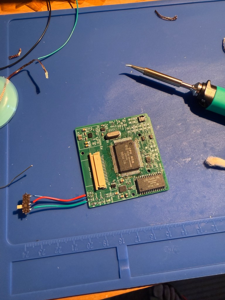
And yep, it fits! I’m super proud of the clean look. Now off to soldering land to get the MGB CPU and RAM scavenged and integrated onto the new board.
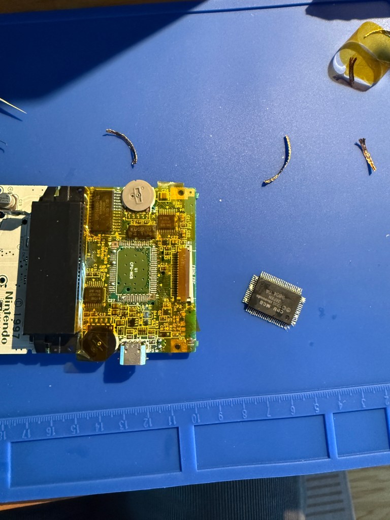
This was my first time desoldering an MGB CPU and I’ve got to say I was super nervous. I used my heat gun to heat up the CPU perimeter with little success. I tried desoldering wick and also struggled with that. Then I thought hmm.. maybe I could use some solder paste with the heat gun to increase the thermal mass. That worked like a charm! Basically the solder paste stored a ton of the heat and it basically gave me more time to flow the solder around and eventually led to removal of the CPU. This approach wasn’t the cleanest and required clean up of the CPU pins but did the trick nonetheless. I used the same approach on removing the RAM. I will say I did blast a ton of heat at these ICs and I was nervous that they would even work.
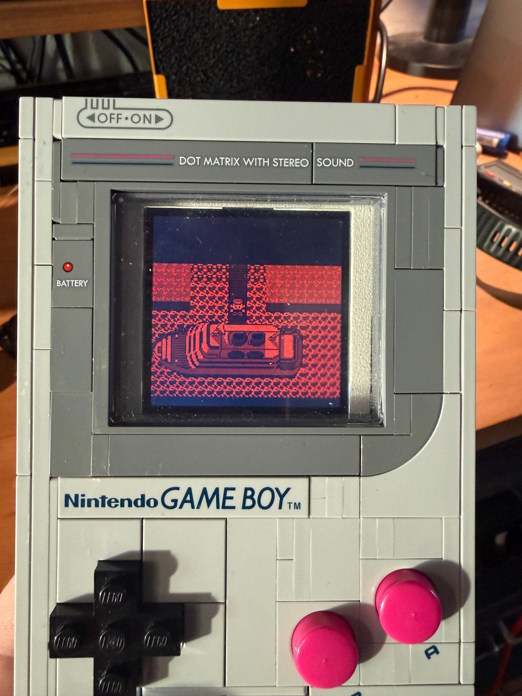
Voila! Now will things power up??
Here’s my first power on test with a game cartridge. You can see the lovely Nintendo logo drops down but then it fades off into the abyss.. hmm what’s going on here? Did I mess something up?
The Gameboy CPU has a specific boot process. If a game cartridge is detected it, it displays the Nintendo logo and then performs a checksum with the RAM. This meant that the CPU was most likely okay and wired up properly, but there was something going on with the RAM. I disconnected everything and took a closer look. As it turned the leg on one of the RAM joints was lifted off the solder pad! I fired up my soldering station again and then inspected all the pins one last time.
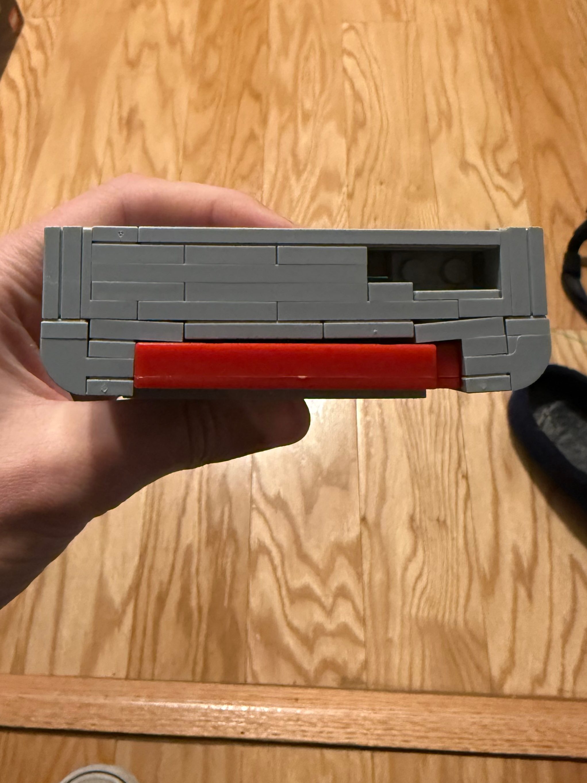
The final step was getting the screen, screen conversion board and gameboy PCB all packaged inside the dimensions of the screen housing. One main requirement I set out for was that there could be no glue or adhesive involved. I wanted something that could be dropped in like a lego brick. The build process should be fun and I believed adhesives would take that away. After multiple iterations and getting things to fit I finally ended up with a screen module design where all these components were stacked in one neat 3D printed housing package. The module was designed to connect to some existing lego studs inside the housing and then is further constrained by use of the existing cutout for the contrast wheel.

Leave a comment